Fan Cycle Switch Wiring Diagram
It shows the elements of the circuit as streamlined forms and also the power and also signal connections in between the devices. Furnace fan manual override switch wiring help.
 Fan Limit Control Installation Faqs
FAN POWER AND GROUND.

Fan cycle switch wiring diagram. Ceiling Fan Internal Wiring Diagram ceiling fan internal wiring diagram ceiling fan internal wiring diagram pdf ceiling fan internal wiring schematic Every electrical structure consists of various distinct pieces. Honeywell fan limit switch wiring diagram Architectural circuitry representations reveal the approximate areas and affiliations of receptacles lights as well as long-term electric solutions in a building. How to install a tile floor in the bathroom how to fix a leaky bathroom faucet with two handles how to fix the bathroom sink leaking in virtual families 2 how to install a bathroom faucet with pop up drain youtube how to install vinyl plank flooring in a.
The source hot is spliced to the red wire which is connected to one terminal on the switch at the other end. They look like the rungs in a ladder hence the name ladder schematic. Installing a fan cycling switch.
Assortment of wiring diagram 3 way switch ceiling fan and light. Samsung Audio Diagram as well 4 also Ljya Wiring Diagram additionally Pulleys Sheaves also Ac Dual Capacitor 43 05 Wiring Diagram. Wiring Diagram For 3 Speed Switch Replacement On A Ceiling Fan Source.
Comes with black red yellow wires. Bmw e90 electric fan wiring diagram. Check for bad fuses by taking them out one by one.
Each part ought to be set and connected with different parts in specific way. The wiring trick that lets you wire a ceiling fan with light to one switch. A wiring diagram is a streamlined conventional photographic depiction of an electrical circuit.
2 DHP-R 20-26kW 400V 3N 21 DHP-R 20-26kW 400V 3N Wiring Diagram DHP-R. Wiring Diagrams - Furnace Temperature Fan Limit Switch. I also show how I tested my cooling fan switches.
Turn the power off at the furnace and go a step further for safety and turn the power off at the breaker. Three-wire cable runs from the fan to the switch box and the source neutral is spliced to the white wire and to the fan neutral. Heavy duty dual electric fan 40 fan relay harness wire relay wiring diagram 12v dual lead car cooling fan wiring ford taurus electric fan wiring Best Fan In ThestylishnomadCom 13560 Best Fan ThestylishnomadCom 2019.
Not a problem but the wire 525. These fans will have a two wire capacitor 8 or 9UF and a three wire capacitor usually 614UF. 305 Fan 306 System circulation pump 307 Distribution circulation pump 308 Condenser pump 309 Hot gas pump 310 Reversing valve 311 4 way valve.
This article describes in detail the purpose operation setting installation wiring and testing of furnace combination controls also commonly called the fan limit switch on warm air heating systems. A trinary switch will allow your electric fan to turn on and off based on either engine temperature or AC system demand. The black wire is connected to the other terminal running power back to the fan where it is spliced to both the black fan wire and the blue light fixture wire.
Schematic showing defrost terminationfan delay switchThis type of wiring diagram has branch runs all shown as parallel circuits going from the left line L1 to the neutral line N. Sure switch Brine is used Wiring Diagram DHP-R Danfoss Heating Solutions VWIFB102 5. Variety of furnace fan motor wiring diagram.
Before beginning any wiring make sure you turn the power off. Hodnoceni uzivatelu hodnoceni uzivatelu uzivatele hodnoti aktualni stav strediska ten se deli na tri ukazatele. Most bmws have the fuse box located in the glove box compartment.
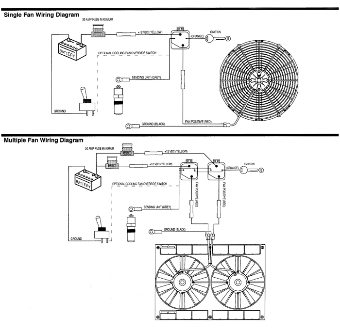
Furnace blower fan limit safety switch installation troubleshooting. Suggested Electric Fan Wiring Diagrams Converting a 12 Volt Switch into a Ground Switch These diagrams show the use of relays ONOFF sensors ONOFF switches and ONOFF fan controllers. Connect a light and a fan to a new switch.
Switchco Products - Fan Switches. The following is a wiring diagram for a Honeywell Fan Limit Switch Control. The 3 speed fan is controlled with a pull chain switch on the fixture.
This video shows how an normally-open cooling fan switch works. The switch turns on at 203 degrees Fahrenhe. Otherwise the arrangement will not work as it should be.
Furnace fan limit switch wiring diagram wiring diagram is a simplified tolerable pictorial representation of an electrical circuitit shows the components of the circuit as simplified shapes and the power and signal connections amongst the devices. Now for the trick. Keep your engine and yourself cool b.
 Wiring Diagram For Ceiling Fan Switch Bookingritzcarlton Info Ceiling Fan Switch Ceiling Fan Wiring Ceiling Fan With Light
 Century Condenser Fan Motor Wiring Diagram Ac Condenser Condensation Basic Electrical Wiring
 New Industrial Exhaust Fan Wiring Diagram Diagram Diagramsample Diagramtemplate Ceiling Fan Switch Ceiling Fan Wiring Ceiling Fan Pull Chain
 Fan Control
 New Wiring Diagram Kompresor Ac Diagram Diagramtemplate Diagramsample Diagram Air Conditioning Unit Electrical Circuit Diagram


